Paper, PDF, DXF, STEP: what arrives with an order
Each format gives you something and hides something else. What you can rely on in each, how Metallovy handles it today, and what to ask the customer for.
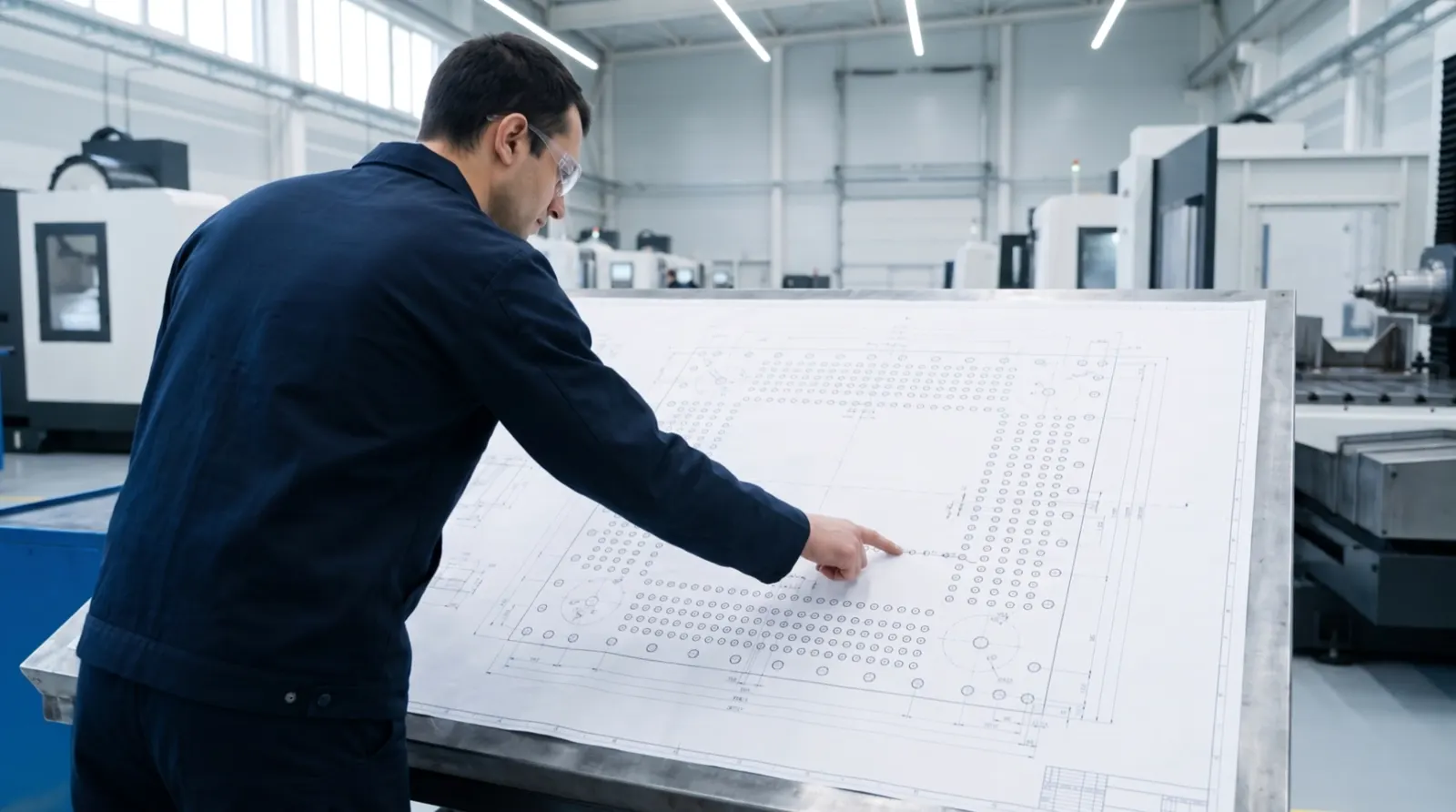
An order arrives. Sometimes it is a paper print, most often a PDF, sometimes a DXF and a STEP model together. Not one of them comes with what the machinist actually needs: hole positions from their own zero, by group, with depth and side, ready for the control.
What you can do next depends on the format. Here is what each one gives you, what it leaves out, and how Metallovy treats it today.
At a glance
| Format | What it gives you | What it leaves out | Metallovy today |
|---|---|---|---|
| Paper | Dimensions, tolerances, notes, the designer’s intent | Any digital geometry; often some dimensions | Scans and photos: in development |
| The whole drawing, notes and hole table; easy to send | A model; reliable geometry if it is a scan | Claude reads it and builds the part; the engineer confirms | |
| DXF | Exact 2D geometry: circle centres, diameters, texts, the hole table | Depth, side and through or blind live only in callouts; views are scaled | Available |
| STEP | The whole part or assembly in 3D: every hole with its axis, start and end | Thread details, tolerances and notes stay on the drawing | Available |
Paper
A print carries everything the designer meant, and nothing a computer can measure. Two things cause trouble. Some holes have no dimension at all, because the designer had the model and didn’t need one. And a print is not a measuring instrument: copying, folding and scanning all change the scale.
Reading scans and photos of paper drawings is in development in Metallovy. When it arrives, any value measured off the picture will be marked approximate and will not pass into a program as exact. Until then, for a plate with holes, the engineer can give the assistant the dimensions from the print, and it builds the part with exactly those numbers.
The most common case. A PDF exported from CAD is a vector drawing; a PDF of a scan is just a picture. Either way it holds the whole drawing: views, the hole table, callouts, the revision block.
Today, Claude reads the PDF the way a person would, sheet by sheet, and builds the part from the dimensions it read, with the source of each value. The part is marked “not verified” until the engineer has checked it against the sheet and pressed “Checked, confirm”. Until then, downloading the program shows a warning. This only happens in jobs where sending data to the cloud AI is allowed. Reading the vector geometry of a PDF directly, without AI, is planned.
DXF
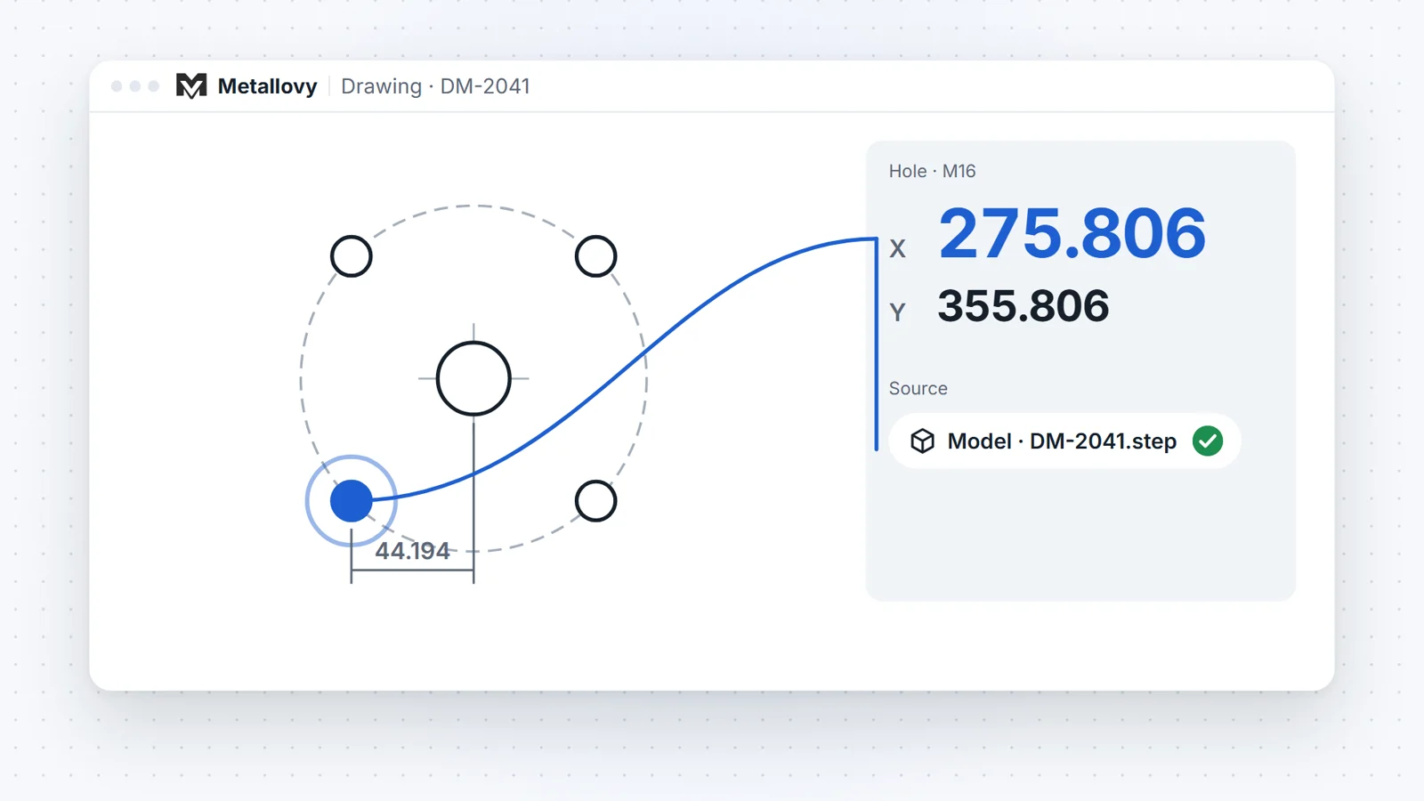
A DXF gives you real geometry. Circles have exact centres and diameters. Dimensions, callouts and the hole table are text that can be read. That is enough to find every hole on a view and the group it belongs to.
What a DXF doesn’t give you is the third dimension. Depth, which side a hole is on and whether it goes through all live in the callouts and the hole table, if they are there at all. Views are also scaled: a 1:5 view drawn in sheet units has to be converted before a single coordinate is right.
Metallovy reads the DXF sheet: it finds the view and its scale from the title block, reads the hole table and the callouts on the holes, and groups the holes accordingly. It can also export a DXF back, with your zero and labelled coordinates, for anyone who wants to check in AutoCAD.
STEP
A STEP model is the best thing a customer can send. Every hole is a cylinder with an axis, a diameter, a start and an end, so through or blind is no longer a question. For a welded part, the assembly says where each welded pad or strip sits on the base part.
What a model usually doesn’t carry: threads are often modelled as plain cylinders, at tap drill or nominal size, with the thread itself only a cosmetic feature or a note. Tolerances, surface finish and notes are on the drawing.
Metallovy reads the STEP model with its own code: holes, depths, through or blind, and the assembly. That is where you set up the job: the base part, the welded parts machined with it, the side you are working on, and where the zero is. The 3D view shows each hole, top or bottom, through or blind.
The best case: both
A drawing and a model of the same revision check each other. The model gives exact positions and hole lengths; the drawing gives threads, depths from the hole table and tolerances. When the callout says 4x and the model has four, good. When it has three, somebody needs to know before the part is on the machine.
That is how Metallovy reached 68 of 68 points of a shop’s own program on a real order, within 0.01 mm.
What to ask the customer for
Most customers will send more if you ask. A short list:
- The 3D model as STEP (AP214 or AP242), of exactly the same revision as the drawing. For a weldment, the whole assembly, not only the base part.
- The drawing as DXF or DWG, same revision.
- A PDF exported from CAD, not a scan of a print.
- The revision history: what changed since the last version you machined.
- The datums: which faces and edges the dimensions start from, if the drawing doesn’t make it obvious.
- Any missing dimension in writing, rather than measuring it off a print.
- What you may do with the files: who may see them, and whether cloud processing is allowed.
A line that works in an email: “Could you also send the STEP model and the DXF of revision C, the same revision as the PDF? Then we can take the hole positions from the geometry instead of retyping them.”
Try it on one of your own drawings, and if you have the model, bring that too.